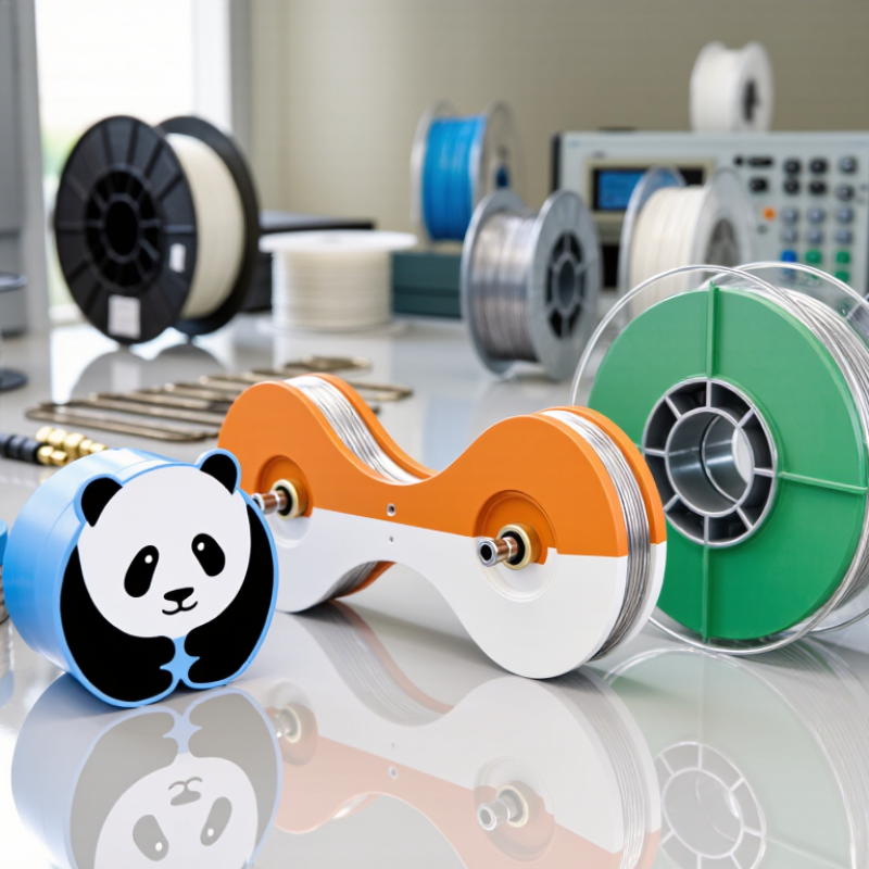
Choosing the right Polarization-Maintaining Fiber in 2026 requires more than comparing prices or catalog photos. Fiber geometry, operating wavelength, extinction ratio, beat length, and bend sensitivity can change real-world performance. A fiber designed for 1550 nanometers may not suit a 780-nanometer interferometer. Small differences matter.
This guide examines widely used types, including panda, bow-tie, and elliptical-cladding designs. It connects manufacturer specifications with practical buying conditions, such as connector quality, spool length, environmental stability, and coupling loss. Reliable selection should begin with the application, not the marketing label. For example, a fiber gyroscope may prioritize low polarization crosstalk, while a coherent communication system may require tighter attenuation and return-loss control. That distinction is easy to overlook.
The strongest recommendations should come from verifiable datasheets, test reports, and application evidence. Check whether quoted extinction ratios were measured at your wavelength and under comparable temperature conditions. Ask for tolerances, not only typical values. Vendors sometimes emphasize impressive laboratory results. Those results may not represent a finished assembly.
No single fiber type is best for every project. That is the inconvenient part. Budget limits, delivery schedules, packaging, and field handling can influence the final decision. This 2026 buying overview offers a structured comparison, while recognizing that specifications can vary between manufacturers and production batches. Before ordering, confirm compatibility with your source, detector, connectors, and required polarization stability. A careful purchase begins with measurable requirements and ends with independent verification.
Polarization-maintaining (PM) fiber is designed to keep light’s polarization stable during transmission. Unlike standard single-mode fiber, it contains built-in birefringence between two perpendicular axes. This difference makes one polarization direction travel slightly faster than the other. The fiber core is supported by stress-applying regions, often called panda or bow-tie structures. These regions create mechanical stress around the core. The stress separates the two polarization modes and reduces unwanted rotation.
Alignment matters.
When polarized light enters the correct slow or fast axis, it remains substantially aligned through the fiber. However, PM fiber does not actively correct poor installation or careless handling. Bending, twisting, connector misalignment, and temperature changes can reduce the extinction ratio. In laboratory testing, even a small angular error may produce visible power leakage into the unwanted axis.
A proper setup uses polarization-axis markings, controlled stripping, and carefully polished connectors. The result depends on the complete link, not only the fiber specification.
The main PM fiber types include stress-birefringent designs and geometrically birefringent designs. Stress-based fibers are widely used in interferometers, fiber sensors, gyroscopes, and coherent optical systems. Elliptical-core designs can offer strong polarization separation, but their handling requirements may differ. When choosing a fiber in 2026, check beat length, extinction ratio, operating wavelength, coating temperature range, bend tolerance, and connector orientation. Attenuation alone is not enough. I would also question unusually perfect specifications, because real performance depends on splicing skill and mechanical installation. Some datasheets explain this poorly.
Polarization-maintaining fiber is available in several practical designs.
PANDA fiber uses stress-applying regions beside the core. It offers strong birefringence and stable polarization performance.
Bow-tie fiber uses shaped stress elements around the core. It can provide efficient polarization control in compact optical systems.
Elliptical-core fiber creates birefringence through an intentionally non-circular core. This design may suit sensing and interferometric applications.
Side-hole fiber is another option for specialized sensing, especially where environmental response matters.
Selection should match the actual system, not only the specification sheet. Check beat length, polarization extinction ratio, insertion loss, wavelength range, and coating compatibility.
PANDA designs often suit gyroscopes, coherent links, and laboratory instruments.
Bow-tie designs can support compact assemblies and demanding polarization routing.
Elliptical-core designs may help when mechanical simplicity matters.
In practice, connector stress and bending can reduce performance. That detail is easy to underestimate. A perfect datasheet does not guarantee a perfect installation.
Tips:
Confirm the operating wavelength first. Ask for test conditions behind every quoted value. Review bend sensitivity, proof strength, and connector options. Buy a short sample before committing to a long fiber run. Also, allow measurement uncertainty. Real systems are less tidy than laboratories.
Choosing the best polarization-maintaining fiber in 2026 requires more than comparing attenuation. PANDA, bow-tie, elliptical-core, and spun PM designs behave differently under bending, temperature changes, and connector stress. Check extinction ratio, beat length, mode-field diameter, coating type, and operating wavelength. MarketsandMarkets’ 2024 optical fiber report forecasts strong market growth through 2030, driven by data centers, sensing, and high-speed networks. This growth increases compatibility risks between fibers, connectors, and optical components.
A reliable comparison should include real test results, not only typical values. Verify insertion loss, polarization crosstalk, bend performance, and extinction-ratio stability after thermal cycling. IEC 60793-2-50 defines categories for polarization-maintaining fibers, while IEC 60793 and Telcordia testing practices support mechanical and environmental evaluation. In laboratory work, matching mode-field diameter often prevents more trouble than choosing the lowest attenuation. A perfect datasheet is not enough. Connector polishing, cleave angle, and alignment can weaken field performance. I would also request samples, because catalog values may not represent long cable assemblies.
Tips:
Compare fibers at your actual wavelength. Confirm connector and coating compatibility early. Test several samples under heat, humidity, and repeated bending. Keep results in a traceable test log. If polarization extinction falls sharply after assembly, investigate the process before blaming the fiber. That mistake is common, and sometimes justified.
2026 Best Polarization-Maintaining Fiber Types to Buy?
Which PM Fiber Type Fits Different Applications and System Designs?
Choosing a polarization-maintaining (PM) fiber starts with the system, not the catalog. Check wavelength, required extinction ratio, bend radius, and connector alignment. A laboratory interferometer may prioritize low phase noise. A compact gyroscope may need stable polarization under vibration. These requirements can point to different fiber structures.
Panda-style and bow-tie fibers use internal stress elements to create strong birefringence. They suit telecommunications, fiber sensors, interferometers, and many narrowband optical systems. Panda-style designs often provide balanced performance and easier handling. Bow-tie structures can deliver high polarization stability, but splicing demands careful axis alignment. Small errors matter.
Elliptical-core fibers create birefringence through geometry. They can fit sensing systems that need a simple, stress-free design. PM photonic crystal fibers are more specialized. Their air-hole structure supports unusual dispersion, high power handling, or broad spectral transmission. Large-mode-area PM fibers may reduce nonlinear effects, yet they usually require larger components and stricter launch control.
For a 1550 nm communication link, a standard stress-induced PM fiber is often practical. For precision sensing, compare beat length, thermal sensitivity, and long-term drift. For high-power pulsed work, inspect damage thresholds and mode quality. I have seen specifications look excellent until connector rotation exposed poor axis matching. That detail is easy to underestimate. Test the complete assembly, not only the bare fiber. 恒一
| PM Fiber Type | Polarization-Maintaining Structure | Typical Operating Wavelengths | Typical Beat Length | Typical Attenuation Range | Key Advantages | Main Limitations | Best-Fit Applications and System Designs |
|---|---|---|---|---|---|---|---|
| Bow-Tie PM Fiber | Two stress-applying parts are positioned on opposite sides of the fiber core. The induced stress creates strong birefringence between the two principal axes. | Commonly available for approximately 780 nm, 850 nm, 980 nm, 1060 nm, 1310 nm, and 1550 nm designs. | Typically about 1–3 mm, depending on wavelength and fiber design. | Commonly about 0.3–3 dB/km near the intended operating wavelength. | High polarization extinction capability; mature design; good axis definition; suitable for many standard PM passive components. | Stress structure can increase sensitivity to bending, coating conditions, temperature, and connector alignment. | A strong general-purpose choice for fiber interferometers, gyroscopes, polarization-sensitive sensors, coherent links, PM patch assemblies, and laboratory optical systems. |
| Panda PM Fiber | Two circular stress-applying rods are placed symmetrically beside the core. The geometry produces birefringence while retaining a relatively simple circular fiber profile. | Commonly designed for 780 nm, 850 nm, 980 nm, 1060 nm, 1310 nm, and 1550 nm. | Typically about 1–5 mm, with the exact value determined by the stress-rod geometry and glass composition. | Commonly about 0.2–2 dB/km in the specified operating band. | Good mechanical handling; relatively consistent geometry; widely used for polarization control and component pigtails. | Polarization performance can vary with bend radius, temperature, splicing, and the quality of axis alignment during assembly. | Well suited to integrated optical modules, interferometric sensors, PM couplers, fiber lasers, coherent receivers, and compact systems requiring practical splicing and handling. |
| Elliptical-Core PM Fiber | The fiber core has an intentionally elliptical shape. Form birefringence separates the two orthogonal polarization modes without relying primarily on external stress rods. | Often optimized for visible, near-infrared, or specialized wavelength bands, including approximately visible 630–780 nm and near-infrared 850–1550 nm. | Frequently around 1–10 mm, depending on the ellipticity and core design. | Commonly about 0.5–5 dB/km, with specialty versions potentially higher. | Simple birefringent concept; can provide strong polarization separation; useful where a non-circular mode profile is acceptable. | Elliptical mode shape can complicate coupling, connectorization, splicing, and compatibility with standard circular-core components. | Best for specialty sensors and custom optical assemblies where polarization discrimination is important and the system can accommodate a non-circular mode field. |
| Side-Hole or Side-Tunnel PM Fiber | Air holes or low-index regions are formed beside the core. The asymmetric geometry creates high birefringence and can also enable interaction with the surrounding environment. | Commonly produced for visible and near-infrared operation, with designs frequently covering approximately 633–1550 nm. | Often below 2 mm in high-birefringence designs, but the value is highly dependent on hole geometry and wavelength. | Frequently about 1–10 dB/km; specialty structures may have higher loss. | Very strong birefringence potential; useful for compact polarization devices, sensing, and designs requiring access to the optical field. | More difficult fabrication and cleaving; higher loss and greater packaging sensitivity are common compared with conventional solid-glass PM fibers. | Suitable for advanced sensing and research systems, including pressure, strain, temperature, chemical, microfluidic, and polarization-selective specialty devices. |
| Photonic Crystal PM Fiber | A periodic air-hole cladding and an intentionally asymmetric core or hole arrangement create birefringence and guide light by modified total internal reflection or related mechanisms. | Available in specialty designs from the visible range through the near-infrared; operating wavelength is strongly design-specific. | Often approximately 0.5–5 mm, although specialized structures may fall outside this range. | Commonly about 1–20 dB/km, with performance varying greatly by design, wavelength, and fabrication quality. | Flexible control of mode area, dispersion, birefringence, nonlinear response, and wavelength range; supports highly customized optical behavior. | Higher cost and integration complexity; coupling, cleaving, splicing, connectorization, and environmental packaging require careful engineering. | Best for research, nonlinear optics, ultrafast lasers, specialty spectroscopy, and custom high-performance systems where standard PM fiber cannot meet the design targets. |
| Polarization-Maintaining Single-Mode Fiber | A single-transverse-mode fiber with deliberately high birefringence, commonly implemented using bow-tie, panda, elliptical-core, or related structures. | Selected for the system band, commonly 780–1060 nm, 1310 nm, or 1550 nm. | Usually about 1–5 mm for conventional high-birefringence designs. | Often approximately 0.2–3 dB/km in the intended operating band. | Predictable fundamental-mode behavior; straightforward integration with PM lasers, modulators, detectors, and passive components. | Does not automatically preserve polarization after poor splicing, excessive bending, connector misalignment, or operation outside the specified band. | The default choice for most polarization-sensitive single-mode architectures, including coherent communications, fiber sensors, interferometers, and precision measurement systems. |
| Polarization-Maintaining Large-Mode-Area Fiber | A PM structure is combined with a larger effective mode area to reduce optical intensity and nonlinear effects while maintaining polarization discrimination. | Commonly designed for approximately 1.0–1.1 µm and 1.5–1.6 µm systems, with other specialty wavelengths available. | Typically about 1–10 mm, depending on the required polarization stability and mode-field diameter. | Commonly about 0.5–5 dB/km; high-power specialty designs may trade loss against mode area and handling performance. | Higher power-handling capability; reduced nonlinear phase accumulation; useful for narrow-linewidth and high-energy polarized sources. | More sensitive to bending and higher-order mode excitation; alignment and launch conditions are more demanding than for standard PM single-mode fiber. | Recommended for high-power fiber lasers, amplifiers, coherent beam delivery, and low-nonlinearity systems requiring linearly polarized output. |
| Polarization-Maintaining Multimode Fiber | A birefringent fiber supports more than one spatial mode while maintaining preferential polarization axes. Polarization stability is therefore coupled to modal control. | Typically selected for visible, 850 nm, 980 nm, 1060 nm, or 1550 nm systems, depending on core size and application. | Often about 1–10 mm, with the effective value depending on the guided modes. | Commonly about 1–10 dB/km, depending on core diameter, numerical aperture, wavelength, and mode-management requirements. | Supports higher optical power or relaxed coupling requirements than single-mode PM fiber; can provide larger mode area. | Modal dispersion and differential modal behavior can reduce polarization stability and system bandwidth; mode control is essential. | Use selectively for high-power delivery, specialty illumination, imaging, and systems where modal behavior is characterized and acceptable. |
| PM Fiber for Fiber-Optic Gyroscopes | Usually a low-loss, low-birefringence-drift PM design optimized for long sensing coils, stable polarization axes, and low polarization cross-coupling. | Frequently optimized around 1310 nm or 1550 nm, depending on the gyroscope architecture and optical source. | Commonly selected in the approximate range of 1–4 mm for coil applications. | Often targeted below approximately 1 dB/km in high-performance designs, although the required value depends on coil length and architecture. | Low polarization cross-coupling; suitable for long coils; can support stable interferometric measurements when winding and thermal behavior are controlled. | Coil winding stress, temperature gradients, radiation, connector losses, and splice quality can significantly affect bias stability and scale-factor performance. | Best suited to navigation-grade and precision interferometric fiber gyroscopes when accompanied by qualified coil winding and environmental testing. |

Before buying polarization-maintaining fiber in 2026, define the operating conditions clearly. Check the required wavelength, beat length, mode-field diameter, and attenuation. A fiber designed for 1550 nm may perform poorly near 1310 nm. That mistake is easy.
Confirm how polarization extinction ratio is measured. Test conditions matter, including launch alignment, fiber length, temperature, and connector quality. Ask for complete datasheets and recent inspection records, not only headline specifications. Reliable suppliers should provide batch information, tolerance ranges, and testing methods. If the application uses splicing, review splice loss and polarization-axis alignment carefully. Tiny angular errors can weaken system stability.
Environmental performance deserves equal attention. Check operating temperature, bend sensitivity, coating material, humidity resistance, and expected storage conditions. For sensors or interferometers, vibration response may matter more than the lowest attenuation. For compact equipment, compare bend-insensitive and standard polarization-maintaining structures. They are not interchangeable in every design. I once focused too heavily on extinction ratio and overlooked connector repeatability. The purchase looked efficient, but integration became slower. That experience still shapes my checklist.
Request sample lengths before placing a large order. Measure insertion loss and polarization behavior with your own instruments. Compare results at room temperature and across the intended temperature range. A short trial can expose unstable connectors, inconsistent axes, or unexpected handling limits. Also examine lead time, technical support, and replacement availability. Specifications build confidence, but verified performance earns it.


All of Hapco's formulations are completely free of Mercury.

Hapco has been in business for over 50 years!
*NOTICE* Hapco will be will be closed on Monday, May 26th, in observance of Memorial Day. |
| Cookie | Duration | Description |
|---|---|---|
| cookielawinfo-checkbox-analytics | 11 months | This cookie is set by GDPR Cookie Consent plugin. The cookie is used to store the user consent for the cookies in the category "Analytics". |
| cookielawinfo-checkbox-functional | 11 months | The cookie is set by GDPR cookie consent to record the user consent for the cookies in the category "Functional". |
| cookielawinfo-checkbox-necessary | 11 months | This cookie is set by GDPR Cookie Consent plugin. The cookies is used to store the user consent for the cookies in the category "Necessary". |
| cookielawinfo-checkbox-others | 11 months | This cookie is set by GDPR Cookie Consent plugin. The cookie is used to store the user consent for the cookies in the category "Other. |
| cookielawinfo-checkbox-performance | 11 months | This cookie is set by GDPR Cookie Consent plugin. The cookie is used to store the user consent for the cookies in the category "Performance". |
| viewed_cookie_policy | 11 months | The cookie is set by the GDPR Cookie Consent plugin and is used to store whether or not user has consented to the use of cookies. It does not store any personal data. |