What Is a Canned Motor Pump and How Does It Work?
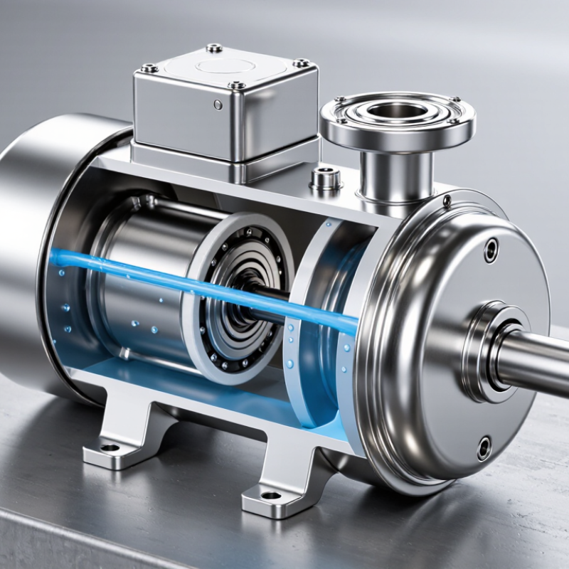
A Canned Motor Pump moves liquid without a conventional shaft seal. Its motor and pump share one sealed housing. The pumped liquid flows through the unit, cooling the motor and lubricating its bearings. Imagine a compact stainless-steel body, warm to the touch, with no external shaft emerging from its casing. That enclosed design helps prevent leakage, an important benefit when handling costly, hazardous, or sensitive fluids.
Igor J. Karassik, a pump engineer and co-author of the Pump Handbook, offers a useful general lesson for pump selection: “Match the pump to the service it must perform.” This is a paraphrase of his engineering guidance, not a verified verbatim quotation about canned motor pumps. The distinction matters. A pump’s suitability depends on the liquid, operating temperature, pressure, and flow requirements—not merely its name or construction.
Inside a canned motor pump, the rotor turns within a thin containment shell, while the stator remains isolated from the pumped liquid. This eliminates the usual dynamic shaft seal, but it does not make the equipment maintenance-free. Bearing wear, dry running, and unsuitable fluid properties can still cause trouble. Quiet operation. Fewer leak paths. Yet one detail is easy to overlook: the liquid often serves as both process fluid and lubricant. Understanding that trade-off makes the pump’s design easier to evaluate, and its limits harder to ignore.
Defining the Canned Motor Pump Under API 685
A canned motor pump is a sealless centrifugal pump with its impeller and motor rotor mounted on a shared shaft. The pumped liquid enters the pump casing and circulates through the motor cavity. A thin containment shell separates the liquid from the stator windings. No rotating shaft passes through the pressure boundary, so there is no conventional dynamic shaft seal. That distinction matters. It reduces one potential leak path, but does not remove the need for careful system design.
API 685 is the industry standard for sealless centrifugal pumps used in petroleum, petrochemical, and natural gas services. It establishes requirements for matters such as design, materials, inspection, and testing. A canned motor pump may fall within its scope, but the label alone does not prove compliance. The applicable edition, operating conditions, and agreed purchase specifications matter. Check these details against the project documents. Even a well-made pump can be a poor fit if its temperature, pressure, or liquid properties exceed the specified limits.
During operation, a portion of the pumped liquid typically cools and lubricates the motor bearings before returning to the pump flow. The arrangement is compact, with no external coupling guard or seal-flush piping to crowd the installation. But the liquid must suit this internal circulation. Solids, poor lubricity, or vapor formation can create problems. The details deserve a second look. A simple cross-section drawing may not show every operating concern.
Tracing the Drive: 2-Pole Motors Run at 3,000 rpm at 50 Hz
At 50 Hz, a two-pole motor produces a rotating magnetic field at 3,000 revolutions per minute. The calculation is synchronous speed = 120 × frequency ÷ pole count, as set out in IEC 60034-1. This is the field’s speed, not always the rotor’s exact speed. In an induction motor, the rotor runs slightly slower so it can produce torque. That difference is called slip.
Inside a canned motor pump, the rotor sits within a sealed containment shell, eliminating the conventional shaft seal. The motor’s magnetic field drives the rotor and impeller together. At 3,000 rpm, the impeller can deliver substantial flow from a compact assembly, but speed alone does not define performance. Flow, head, liquid properties, and operating load all matter. Small details matter.
A useful industry context comes from the International Energy Agency’s 2011 report, Energy Efficiency Policy Opportunities for Electric Motor-Driven Systems. It estimates that motor-driven systems use about 43–46% of global electricity. That broad figure is a reminder to consider the whole operating system, not just the nameplate speed. A 50 Hz supply sets the field’s pace; actual rotor speed and pump output depend on the motor design and duty point. Real installations are less tidy than the calculation.
What Is a Canned Motor Pump and How Does It Work? — Tracing the Drive: 2-Pole Motors Run at 3,000 rpm at 50 Hz
| Dimension | Typical value or construction | How it works / practical note |
| Pump and motor arrangement | Pump and electric motor form a close-coupled, hermetically sealed unit. | The motor rotor and pump impeller are mounted on a common shaft, so power is transferred without an external coupling. |
| Containment can | A thin, non-magnetic metal can separates the stator from the rotor chamber. | The can provides a static barrier between the pumped liquid and the stator windings; it is not a rotating shaft seal. |
| Shaft sealing | No conventional dynamic shaft seal is required. | This eliminates the usual rotating seal interface, although the pump still needs suitable static joints and connections. |
| Rotor and bearings | The rotor operates inside the sealed rotor chamber; many designs use product-lubricated sliding bearings. | Pumped liquid may circulate through the rotor chamber to lubricate bearings and remove heat. The exact flow path depends on the design. |
| Synchronous speed at 50 Hz, 2 poles | 3,000 rpm | Calculated using ns = 120f/P, where f is frequency in hertz and P is the number of poles. |
| Synchronous speed at 60 Hz, 2 poles | 3,600 rpm | This is the rotating magnetic field’s speed; it is not necessarily the operating speed of an induction-motor rotor. |
| Induction-motor slip | Rotor speed is below synchronous speed when producing load torque. | For illustration only, 2% slip at 50 Hz gives 3,000 × (1 − 0.02) = 2,940 rpm. Actual slip varies with motor design and load. |
| Heat management | Heat is managed through the motor housing and, in many designs, circulation of the pumped liquid. | Required cooling flow and temperature limits are model-specific and should be checked against the pump’s technical documentation. |
| Key operating consideration | The pump depends on the liquid and operating conditions for which it is designed. | Adequate liquid supply, compatible fluid properties, and correct operating conditions help protect bearings and prevent overheating. |
Note: 3,000 rpm is the calculated synchronous speed of a 2-pole rotating magnetic field at 50 Hz. The actual speed of an induction motor is typically lower because of slip.
Following the Process Liquid Through the Cooling and Bearing Circuit
A canned motor pump places the motor and pump in one sealed assembly, with no conventional shaft seal. The pumped liquid often serves as both coolant and bearing lubricant. After entering the pump, some liquid passes through an internal circulation path around the rotor and bearing surfaces. It carries away heat and helps reduce friction. The exact route depends on the pump design.
In many designs, pressure differences move this small flow from the discharge side through the motor chamber and bearings, then back toward the suction side. The flow is modest but important. If it is restricted, heat can build around the rotor or bearings. A technician might check temperature, vibration, and flow conditions; one reading alone rarely tells the whole story. This detail is easy to underestimate.
Tips: Keep the liquid clean and within the pump’s specified temperature and viscosity range. Avoid running the pump dry, even briefly, since the bearings may depend on liquid lubrication. If unusual noise or rising temperature appears, check for blocked passages and confirm operating conditions before assuming a component has failed. The circuit can be less obvious than external piping.
What Is a Canned Motor Pump and How Does It Work?
Illustrative process-liquid temperature along a cooling and bearing circuit
In a canned motor pump, some process liquid circulates through the motor and bearing areas, carrying away heat before returning to the pump’s flow. The temperatures shown are illustrative, not universal; actual values and circuit routing depend on the pump design, fluid, and operating conditions.
Explaining How the Containment Can Separates Rotor and Stator
A canned motor pump places the motor rotor and pump impeller on one shaft inside the pumped liquid. A thin containment can sits between the wet rotor and the dry stator. It keeps liquid away from the stator windings while allowing the stator’s magnetic field to turn the rotor. No rotating shaft passes through the pump casing, so there is no conventional shaft seal to leak.
The can is not just a cover. It must withstand system pressure, resist the fluid, and remain thin enough for magnetic force to cross it efficiently. A small gap matters. Excessive thickness can increase magnetic losses and heat; poor material choice can invite corrosion. Pumped liquid often cools the motor and lubricates internal bearings, so blocked circulation can quickly become a problem. In practice, a review should check fluid compatibility, temperature, and bearing lubrication—not just pressure rating. That detail is easy to miss.
The U.S. Department of Energy’s Improving Pumping System Performance sourcebook reports that pumping can account for 25–50% of energy use in some industrial facilities. That figure is not specific to canned pumps, but it shows why operating efficiency matters.
A containment can prevents one leakage path; it does not make every installation maintenance-free.
Assessing Sealless Design Against Pressure, Temperature, and NPSH Limits
A canned motor pump places the rotor inside the pumped liquid, separated from the motor stator by a thin containment shell. The liquid cools the motor and lubricates its internal bearings. No shaft seal crosses the casing, but the shell must contain full process pressure. API Standard 685 covers sealless centrifugal pumps for petroleum, petrochemical, and gas services. It is a design reference, not a universal pressure or temperature rating. Check the actual pressure-temperature limits for the casing, shell, and wetted materials.
Temperature can quietly consume operating margin. IAPWS water-property data put water vapor pressure near 101 kPa absolute at 100°C, rising to about 476 kPa at 150°C. That rise reduces suction pressure available above vapor pressure. At the hot end, even a modest suction loss can trigger vapor formation, poor cooling, or bearing distress. Small margin. A gauge reading alone is not enough; NPSH calculations require absolute pressure, liquid temperature, and losses through the suction line.
The Hydraulic Institute’s ANSI/HI 9.6.1 guidance treats NPSH margin as application-dependent, rather than one fixed number for every pump. Compare available NPSH with the pump’s tested NPSH3, then account for transients, fouling, and measurement uncertainty. API 685 also provides a framework for evaluating sealless-pump design and operation. A neat datasheet can still hide a rough installation: a warm tank, partly closed valve, or clogged strainer changes the real margin. Recheck conditions at the pump inlet, not only at the process-design point.