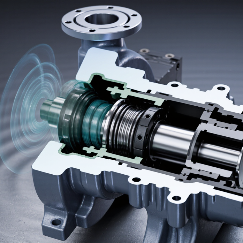
A Face Mechanical Seal is a small component with a demanding job: keeping process fluid contained while rotating equipment runs under pressure, heat, and vibration. The U.S. Department of Energy’s Improving Pumping System Performance: A Sourcebook for Industry reports that pumping systems can account for nearly 20% of global electricity demand. That figure is not a seal-performance measure, but it underlines why sound pump selection and operation matter. A seal that leaks, overheats, or wears early can mean more than a maintenance call.
The right choice depends on the service—not just the pump model. Fluid chemistry, temperature, pressure, shaft speed, solids, and available support systems all shape performance. Reliability author Heinz P. Bloch’s work on rotating equipment points to a useful principle: select for the real operating envelope, not an idealized catalog condition. This is a paraphrase, not a verbatim quotation. Small details count. A flush plan that looks adequate on paper may behave differently with dirty fluid or fluctuating flow. There is no universal best seal.
These seven tips offer a practical starting point: define operating conditions, confirm seal type, check face and elastomer materials, review pressure and speed limits, assess lubrication and cooling, consider installation and maintenance, and verify the supplier’s technical support. They are not a substitute for engineering review. That distinction matters. Even experienced teams can overlook changing startup conditions or fluid contamination. A careful selection process helps reduce avoidable failures, but real service data should always challenge the initial choice.
Define the duty before comparing seal designs. Record pressure at the seal chamber, not only pump discharge pressure. Note normal, startup, shutdown, and upset temperatures. Capture the full RPM range, including variable-speed operation. Describe the process fluid by chemistry, viscosity, solids, gas content, and tendency to crystallize. Small details matter. A clean-looking liquid may still leave deposits after a brief hot shutdown.
The U.S. Department of Energy’s Improving Pumping System Performance sourcebook reports that
pumping systems use nearly 20% of global electricity and 25–50% of energy in some industrial operations.
That figure describes system energy, not seal failure rates, but it shows why operating conditions deserve careful review. API 682 provides a technical framework for mechanical seals in centrifugal and rotary pumps. Compare its guidance with measured site conditions, then check whether pressure and temperature spikes exceed the steady-state values on the datasheet. A spreadsheet can still be wrong if field readings are missing. If the fluid composition changes by batch, document that uncertainty rather than assuming one average value. A few days of logged data can expose a duty the original specification overlooked.

API 682 Category 1, 2, and 3 are not simple low-, medium-, and high-hazard labels. The standard sets seal design and qualification expectations; confirm the applicable edition and equipment scope. For a stable, clean process stream at moderate pressure, Category 1 may be appropriate when the project specification permits it. Hot, flashing fluids, abrasive solids, or frequent temperature swings deserve closer review of Categories 2 and 3. A category number alone does not assess risk.
Tip: Write down the real operating envelope. Include startup pressure, temperature peaks, fluid vapor pressure, solids, and expected cycling—not just normal readings. Then check whether the proposed seal arrangement and support plan suit those conditions. A barrier-fluid plan can matter as much as the category choice. It is easy to over-specify.
Tip: Ask what failure would mean at the site. The U.S. Department of Energy’s Improving Pumping System Performance sourcebook estimates pumping systems account for nearly 20% of global electricity demand. That figure is not a seal-performance measure, but it shows why dependable pump operation matters. Compare lifecycle maintenance, leakage controls, and downtime exposure before selecting a category. I would not decide from the label alone.
A face pair must suit the fluid, operating conditions, and seal design—not just the pump model. Carbon is often chosen for its low friction and gentle running against a hard counterface. It can work well in lubricating liquids, but abrasive particles may wear it quickly. Dry running is risky, too.
Silicon carbide is very hard and resists abrasion and corrosion in many services. It is a common choice when the liquid contains fine solids or offers limited lubrication. However, it is brittle. A sharp impact during installation can chip an otherwise suitable face. Tungsten carbide offers high toughness and wear resistance, which can help with heavier loads or abrasive duty. Its performance depends on the grade and binder, so check chemical compatibility rather than treating all tungsten carbide as identical.
Small details matter.
For a practical comparison, note the liquid’s chemistry, temperature, pressure, solids, and startup frequency. A clean-water duty may favor a different pairing from a slurry service, even on similar equipment. Review the seal maker’s material limits and the pump’s operating record before selecting.
If failures cluster after long shutdowns, startup lubrication may deserve attention. No material fixes poor alignment or inadequate flushing. And charts can be incomplete; actual service history is worth questioning.
For a dual-seal arrangement, set the barrier-fluid pressure 0.14 MPa (20 psi) above the seal-chamber pressure, when the seal design calls for this differential. This positive margin helps keep process fluid from entering the barrier system. Check both readings at the correct measurement points; a gauge elsewhere may show a misleading difference. Small details matter.
Tip: Confirm the required pressure differential in the seal and support-system documentation before startup. Use a regulated supply, and verify the pressure after the pump reaches normal operating conditions. Changes in process pressure can reduce the margin. A steady reading at startup is not enough.
Watch the barrier-fluid level, temperature, and pressure during operation. A falling level or rising temperature may point to leakage, poor circulation, or another issue. Do not raise pressure blindly: excessive pressure can overload the seal or exceed system limits. I have seen readings look reassuring while the reference points were wrong. That is easy to miss. Record operating values, compare them with the specified range, and investigate unexplained changes before they become routine.
Use this checklist to compare seal arrangements and operating requirements. The values below are practical selection guidance, not a substitute for a seal supplier’s limits, applicable standards, or a site-specific engineering review.
| Tip | Selection Dimension | Practical Guidance | Example / Check |
|---|---|---|---|
| 1. Define the process conditions | Pressure, temperature, speed, and fluid state | Record normal, minimum, maximum, and transient conditions. Include start-up, shutdown, flushing, and upset cases because these can change the seal’s operating environment. | Document seal-chamber pressure in MPa or bar, temperature in °C, shaft speed in rpm, and whether the fluid can flash, crystallize, polymerize, or contain solids. |
| 2. Match materials to the fluid | Face pair, secondary seals, and metal parts | Check chemical compatibility and temperature limits for all wetted materials. Common face materials include carbon-graphite, silicon carbide, and tungsten carbide; suitability depends on the fluid, lubrication, solids, and operating conditions. | Confirm compatibility against the actual fluid composition and cleaning agents. Do not select elastomers by temperature rating alone; chemical exposure and pressure cycling also matter. |
| 3. Choose the seal arrangement | Single seal, tandem dual seal, or pressurized dual seal | A pressurized dual-seal arrangement can help contain hazardous or difficult-to-seal fluids when a suitable barrier-fluid system is provided. The arrangement should reflect leakage consequences, process pressure, and monitoring needs. | Specify whether the barrier fluid must be compatible with the process and whether leakage toward the process or atmosphere is acceptable. |
| 4. Set barrier pressure correctly | Barrier pressure relative to seal-chamber pressure | For a pressurized dual seal, a commonly used target is to keep barrier pressure approximately 0.14 MPa (20 psi) above seal-chamber pressure, subject to the seal design and system limits. Maintain positive differential pressure during operation. | If seal-chamber pressure is 0.70 MPa, a nominal barrier-pressure target using this differential is 0.84 MPa. Verify the required differential and maximum pressure with the seal-system design. |
| 5. Select an appropriate barrier fluid | Viscosity, lubricity, thermal stability, and compatibility | Use a clean, stable fluid with suitable lubricating and heat-transfer properties. Check compatibility with the process, seal materials, and any environmental or product-purity requirements. | Specify the fluid grade and cleanliness requirements. Consider viscosity changes across the operating temperature range and the consequences of barrier-fluid leakage into the process. |
| 6. Plan heat removal and circulation | Barrier-fluid circulation and temperature control | Provide adequate circulation and heat removal for the seal’s expected heat load. The required system configuration depends on shaft speed, seal size, fluid properties, and operating conditions. | Check that the reservoir or circulation system can maintain the specified barrier-fluid temperature and pressure; include cooling or circulation components where the design requires them. |
| 7. Include monitoring and maintenance | Pressure, level, temperature, leakage, and alarms | Define operating limits and alarm responses for barrier pressure and fluid inventory. A falling pressure or level can indicate leakage, loss of supply, or a system fault and should be investigated promptly. | Record normal readings at commissioning and set site-approved alarm thresholds. Inspect connections, instruments, fluid condition, and pressure-control equipment at planned intervals. |
Engineering note: The 0.14 MPa (20 psi) differential is a commonly applied guideline for some pressurized dual-seal systems, not a universal requirement. Confirm the pressure basis, allowable operating range, barrier-fluid plan, and alarm settings for the specific seal and equipment.
API 682 (ISO 21049) sets requirements for mechanical seal systems in centrifugal and rotary pumps. Before ordering, compare the pump and seal drawings. Check shaft or sleeve diameter, chamber bore, gland bolt circle, setting length, and port locations. Small errors matter. Confirm tolerances and installation dimensions for the specified standard edition; older drawings may miss revisions. Then assess the seal arrangement, materials, and flush plan against pressure, temperature, speed, fluid chemistry, and solids. An API designation alone does not prove suitability for your operating conditions.
The U.S. Department of Energy’s Improving Pumping System Performance sourcebook estimates that pumping systems use nearly 20% of global electricity. It also reports that pumping can account for 25–50% of energy use in some industrial facilities. These figures describe entire pumping systems, not seal performance, but they underline the value of checking fit, leakage control, and maintainability. Use the project-required API 682/ISO 21049 edition, and request qualification records for the actual operating envelope. Do not infer qualification from a matching envelope alone. Field conditions can differ from the design sheet. Record actual start-up frequency, pressure swings, and flush temperatures before approval.
Verify dimensions and qualification against API 682 (ISO 21049).
API 682 classifies seals by Type, Arrangement, and Category, each numbered 1–3. These are classification options, not performance ratings. Confirm the applicable edition, seal configuration, and all mating dimensions against the project specification and approved seal drawings.


All of Hapco's formulations are completely free of Mercury.

Hapco has been in business for over 50 years!

*NOTICE* Hapco will be will be closed on Monday, May 26th, in observance of Memorial Day. |
| Cookie | Duration | Description |
|---|---|---|
| cookielawinfo-checkbox-analytics | 11 months | This cookie is set by GDPR Cookie Consent plugin. The cookie is used to store the user consent for the cookies in the category "Analytics". |
| cookielawinfo-checkbox-functional | 11 months | The cookie is set by GDPR cookie consent to record the user consent for the cookies in the category "Functional". |
| cookielawinfo-checkbox-necessary | 11 months | This cookie is set by GDPR Cookie Consent plugin. The cookies is used to store the user consent for the cookies in the category "Necessary". |
| cookielawinfo-checkbox-others | 11 months | This cookie is set by GDPR Cookie Consent plugin. The cookie is used to store the user consent for the cookies in the category "Other. |
| cookielawinfo-checkbox-performance | 11 months | This cookie is set by GDPR Cookie Consent plugin. The cookie is used to store the user consent for the cookies in the category "Performance". |
| viewed_cookie_policy | 11 months | The cookie is set by the GDPR Cookie Consent plugin and is used to store whether or not user has consented to the use of cookies. It does not store any personal data. |