
Skip to Content

Liquid Molding Monthly

Top 10 Shredder Parts Every Buyer Should Know?

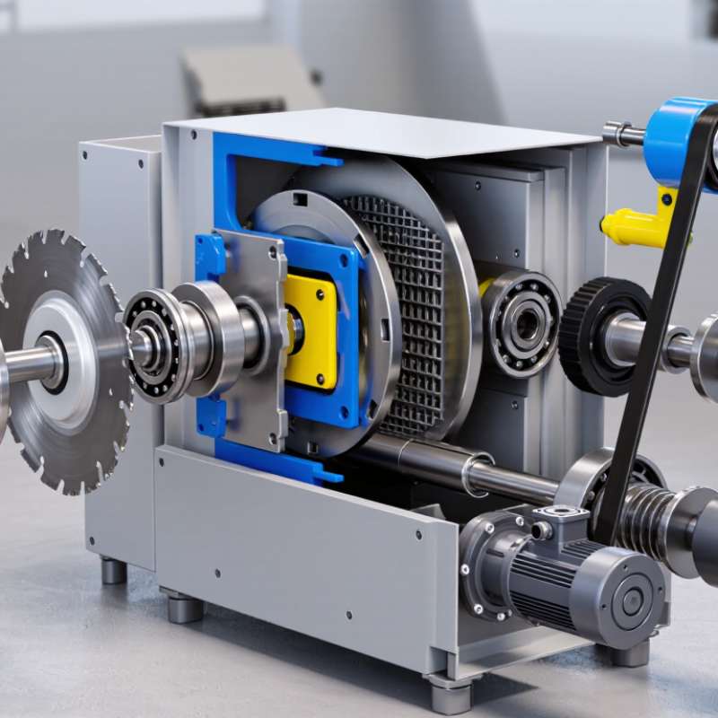
A shredder may look like one machine, but its performance depends on many parts working together. Shredder Parts affect cutting quality, operating noise, maintenance time, and safety. A blade can lose its edge gradually. A bearing may run hot before its failure becomes obvious. Small parts matter. Buyers should know what each component does before comparing prices or ordering replacements.

This guide covers ten parts commonly considered during a purchase or repair: cutting blades, shafts, screens, bearings, motors, gearboxes, belts, seals, fasteners, and safety interlocks. Their importance varies by shredder design and material, so no single parts list fits every machine. Check the model plate, dimensions, material specifications, and manufacturer’s guidance. A screen that looks right may still have the wrong opening size. A low-cost bearing may not suit the machine’s load or operating conditions. Fit matters.

Look for clear product descriptions, traceable specifications, and support from a knowledgeable supplier. Ask how a part affects throughput and what inspection signs suggest wear. A maintenance technician’s notes can help, too; even a simple record of vibration or unusual heat may point to a developing problem. Still, buying decisions are not always neat. Availability, budget, and downtime can pull in different directions. That deserves a second look. The goal is not to replace parts blindly, but to choose components that match the shredder, its workload, and a practical maintenance plan.
Top 10 Shredder Parts Every Buyer Should Know?

Power and Structure: Motor and Supporting Frame

The motor sets a shredder’s usable power, but its rating alone tells only part of the story. Check the rated output, voltage, and duty cycle against the materials and hours of operation you expect. A unit that handles brief runs may struggle during repeated, loaded cycles. Ask whether the motor has suitable overload protection and whether replacement parts are readily available. Small details matter. A clear nameplate and accessible wiring make routine checks less uncertain.

The supporting frame keeps the motor, cutting chamber, and drive components aligned under load. Look closely at welds, mounting points, and any signs of flex around the motor plate. Even slight movement can increase vibration and wear. If possible, inspect the machine while it runs with representative material, not just while it idles. Listen for unusual rattling and watch whether the frame shifts on the floor. That test is not perfect; installation and material differences can change the result. Still, it offers useful evidence. A sturdy frame should also allow practical access for cleaning and maintenance, rather than hiding key fasteners behind awkward panels.


Cutting Mechanism: Blades and Cutter Shafts

The blades and cutter shafts determine how a shredder grips and tears material. Together, they influence throughput, particle size, noise, and power demand. Blade profile matters: hooked edges can pull material inward, while other geometries may suit different feedstocks. Ask which materials the machine is designed to process, and whether its blades are fixed, reversible, or replaceable. Check the cutter shaft’s diameter, support points, and alignment requirements. Even a stout shaft may perform poorly if it flexes or sits out of line. Small details matter.

It is tempting to compare only blade count or thickness, but those figures do not explain steel quality, heat treatment, or maintenance needs. Ask for the recommended clearance between opposing cutters, along with guidance on sharpening and replacement. During inspection, look for chipped edges, rounded tips, cracks near mounting holes, and uneven wear across the shaft. Fresh marks can reveal uneven contact. Measure twice. A specification sheet cannot replace a sample test using representative material. Avoid assuming a heavier cutter is automatically better; it may increase load without improving the cut.

Shredder Cutting Mechanism: Typical Steel Hardness Ranges

Hardness ranges are representative heat-treated values in Rockwell C (HRC), not specifications for every shredder. Blade and shaft selection also depends on toughness, wear, load, and the manufacturer's design requirements.

Material Feeding and Safety: Feed Throat and Interlock

A shredder’s feed throat guides material toward the cutting chamber and helps keep hands away from moving cutters. Its shape and opening size affect how smoothly material enters. A narrow throat may cause bridging, while an overly open design can make safe feeding harder. Check for sharp edges, cracks, loose fasteners, and buildup around the opening. Small details matter. A clean, well-aligned throat supports steady feeding, but it cannot make careless operation safe.

The interlock is a safety device that should stop or prevent operation when an access panel is open. Designs vary, so confirm its intended function in the equipment manual. Test it at the intervals recommended by the manufacturer, and never bypass it to save time. If the machine continues running with a panel open, stop using it and arrange qualified service. Disconnect and isolate power before inspection or maintenance, following the stated procedure. It is easy to assume a switch is working because it clicks; that assumption can be wrong.

Tips: Feed material gradually, without pushing by hand near the throat. Watch for repeated jams or unusual vibration. These can point to a feeding or alignment problem, though the cause is not always obvious.

Top 10 Shredder Parts Every Buyer Should Know? - Material Feeding and Safety: Feed Throat and Interlock

Part Primary Function Buyer Checks Inspection or Service Focus
1. Feed throat Guides material into the cutting chamber and helps limit access to moving cutters. Check opening dimensions, material compatibility, guarding, and whether the throat suits the intended feed method. Look for cracks, deformation, loose fasteners, and material buildup that could obstruct feeding.
2. Interlock switch Monitors an access guard or door and can prevent or stop hazardous operation when it is open, depending on the safety system design. Confirm the switch is suitable for the machine’s safety circuit and that its status is clearly indicated to operators. Test according to the manufacturer’s procedure; never bypass an interlock to keep the machine running.
3. Feed hopper Receives and directs bulk material toward the feed throat or cutting chamber. Review capacity, loading access, wall construction, and compatibility with manual or conveyor feeding. Check for damaged panels, worn liners, loose joints, and unsafe access points.
4. Feed ram or pusher Pushes material toward the cutters on machines designed for ram-assisted feeding. Check ram force and travel against the intended material and confirm that guarding and controls suit the operating cycle. Inspect guides, hydraulic hoses or drive components, and wear surfaces; follow lockout procedures before service.
5. Access guard and guard latch Separates operators from hazardous moving parts and provides a controlled access point for maintenance. Verify that guards are robust, fit correctly, and cannot be opened unintentionally during operation. Check hinges, latches, fasteners, and interlock alignment; do not operate with a damaged or unsecured guard.
6. Emergency-stop device Provides an accessible means to initiate an emergency stop when a hazardous condition occurs. Check device location, visibility, accessibility, and integration with the machine’s control system. Test as specified in the operating instructions and confirm the machine does not restart unexpectedly after reset.
7. Cutter rotor or shaft Carries and drives the cutting elements through the material. Confirm the rotor configuration and working width match the machine duty and material type. Check for abnormal vibration, damage, and bearing or alignment issues; maintenance requires isolation of energy sources.
8. Cutting knives or cutters Shear or tear incoming material into smaller pieces as the rotor turns. Check cutter material, geometry, mounting arrangement, and availability of compatible replacements. Inspect for wear, chipping, looseness, and uneven cutting; replace or rotate only as directed for the machine.
9. Screen or sizing grid Controls the approximate size of material that can pass through the cutting chamber. Choose an opening size suitable for the required output and confirm the screen is compatible with the shredder design. Check for blocked openings, cracks, and wear; clear or remove only after safe machine isolation.
10. Drive motor and transmission Supplies and transfers power to the cutting mechanism. Compare rated power, supply requirements, duty cycle, and drive arrangement with the intended application. Monitor unusual heat, noise, vibration, or leakage; use qualified personnel for electrical and transmission service.

Safety and maintenance requirements vary by machine design. Verify dimensions, replacement-part compatibility, and service procedures against the equipment documentation, and isolate hazardous energy before maintenance.

Drive System: Gears and Bearings

A shredder’s drive system turns motor power into cutting force, and its gears must carry that load without slipping or binding. Gear teeth should mesh evenly; chipped edges, unusual backlash, or metallic debris in the housing deserve attention. Listen during a normal operating cycle. A new growl or rhythmic knock can point to wear, but sound alone does not identify the fault. Check the machine’s service guidance before opening the drive assembly.

Bearings support rotating shafts and help keep the gears aligned. Excessive heat, vibration, or a rough feel during an approved manual inspection may signal damage or inadequate lubrication. Stop the machine and follow its isolation procedure before inspection. Small details matter: grease that looks gritty, a seal that has shifted, or a shaft with visible play can change how the system runs. Not every bearing needs more grease; over-lubrication can also cause problems. That point is easy to overlook. Replacement parts should match the specified dimensions, load rating, and operating conditions. It is tempting to blame the gears first, but a worn bearing can create similar symptoms. Diagnosis takes patience, and sometimes the evidence is not clear on the first check.

Waste Handling and Protection: Bin and Overload Switch

A shredder’s bin is part of its waste-handling system, not just a container. When paper reaches the fill line, scraps can bunch near the cutting head and restrict airflow.

A removable bin should slide into place without force, with its lid or door sitting flush. Check for torn liners, loose fragments, and paper dust around the opening.

Small details matter.

Many models use a bin sensor that stops operation when the container is missing or misaligned. If the shredder will not start, reseat the bin gently and check the indicator light.

Do not bypass the sensor.

Its design varies, so consult the user manual before cleaning or troubleshooting.

It is easy to overlook.

An overload switch helps protect the motor when too much material enters at once or a jam creates excess resistance. Some units stop automatically; others need time to cool or a manual reset.

Unplug the machine before clearing accessible scraps, and never reach into the cutters. Feed smaller stacks, especially when sheets are folded or stapled.

If the switch trips repeatedly, the cause may be dull cutters, a full bin, or feeding beyond the rated capacity. Record what was being shredded when the stop occurred; that simple note can help a technician identify a pattern.

100% Mercury Free

100% Mercury Free

All of Hapco's formulations are completely free of Mercury.

50 Year Track Record

50 Year Track Record

Hapco has been in business for over 50 years!

ISO Certified

Higher Quality. More Efficiency. View Certificate

Technical Expertise

Hapco's employees are knowledgeable and ready to help.

Join Our Mailing List

Get the latest news, updates, and articles from Hapco, Inc.

Join Now